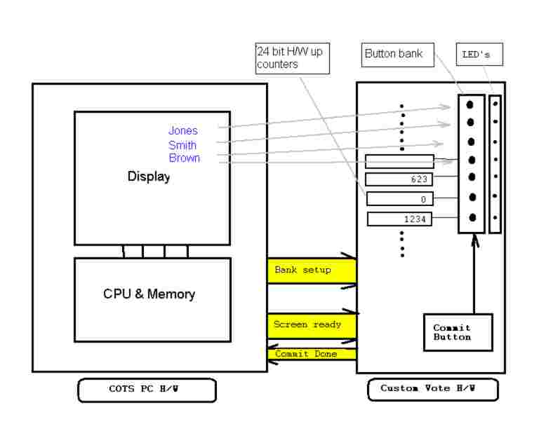
The only communication between the COTS PC and the custom voting logic module is:
- Counter bank setup information, multi-select (w/max permissible selects), or mutual exclusion mode, and an activation map for the buttons to activate.
- A signal that the display information is on screen and the voter should be allowed to start pushing button(s).
- Coming back to the COTS PC is a signal from the voting module that the current bank of selections has been committed
When the voter is done selecting for a particular page of votes, they hit the commit button. This tells the subsystem to strobe the counters corresponding to selections.
An additional (desirable) feature would be the ability to review/change/revisit votes. This feature can be added, by mapping the commit button to a set of bank switched flip-flops that would hold selection information. The addition of a "master commit" button would use the flip-flop banks to strobe the counters rather than the button state flip-flop's themselves. This would require an additional signal to the cots PC to "restart" the vote sequence for a voter.
No comments:
Post a Comment